MIMO Measurements (802.16 OFDMA)
This topic provides information about option IEEE Institute of Electrical and Electronics Engineers. A US-based membership organisation that includes engineers, scientists, and students in electronics and related fields. The IEEE developed the 802 series wired and wireless LAN standards. Visit the IEEE at http://www.ieee.org 802.16 OFDMA STC Space Time Coding (STC) allows the transmitter to transmit signals (information) both in time and space, meaning the information is transmitted by two antennas at two different times consecutively. MIMO Multiple Input, Multiple Output: A physical layer (PHY) configuration in which both transmitter and receiver use multiple antennas. features and measurement capabilities:
- STC MIMO Features
- Making an STC/MIMO Single Channel measurement
- Making an STC/MIMO 2-Channel Measurement
- Matrix Decoder Overview
STC MIMO Features
The VSA IEEE 802.16 OFDMA option provides the following STC MIMO features and capabilities:
- STC/MIMO controls that select the measurement matrix demodulator (Enable Matrix Decoder), which performs STC/MIMO decoding for a single stream of complex data. Matrix decoding is available for Matrix A 2-Ant and Matrix B 2-Ant zone configurations.
- STC/MIMO controls that select the measurement input channel when 2-channel STC/MIMO 2-channel acquisition hardware is available (Measure Input Channel (STC/MIMO)).
- STC/MIMO controls that configure the appropriate antenna selection combined with the input channel selection to determine which antenna path (e.g. Tx1/Rx0) is routed from the overlaid MIMO traces to the existing single channel traces. This allows clearer investigation of a single antenna path.
- Collaborative Spatial Multiplexing (C-SM Spatial multiplexing: a transmission technique in which data streams are transmitted on multiple spatial channels that are provided through the use of multiple antennas at the transmitter and the receiver.) burst analysis (Uplink only): CSM bursts can be defined for UL Up Link (reverse link: from cell phone to base station)-PUSC partial usage of subchannels: Some of the subchannels are allocated to the transmitter. zones by specifying "C-SM" in the "STC Mode" control and selecting the desired pilot pattern (A or B) for the defined burst. Analysis is performed assuming a single transmitter is active.
Making an STC/MIMO Single-Channel Measurement
The following illustration shows a typical single channel, 2-antenna STC/MIMO measurement setup.
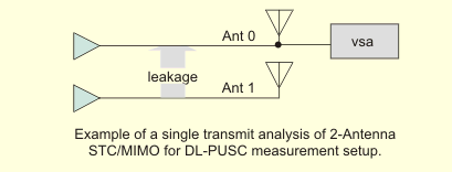
The VSA provides single TX Transmit or transmitter analysis of 2-Antenna STC/MIMO systems.
The VSA can only measure a single antenna port and therefore cannot do MIMO channel estimation. However, using measured power level comparisons of the system antennas based upon the orthogonal locations of the pilots for each antenna, the VSA algorithm can determine the STC/MIMO cross-channel metrics shown in the MIMO Info trace and described below in the "STC Info Summary Table Information" section.
For the VSA to perform STC/MIMO analysis, the antenna 0 signal must also be present for synchronization and DLMAP decoding. One way to accomplish this is to combine RF Radio Frequency: A generic term for radio-based technologies, operating between the Low Frequency range (30k Hz) and the Extra High Frequency range (300 GHz). antenna 0 and RF antenna 1 signals. STC/MIMO analysis is used to evaluate cross-channel leakage and pilot quality. The RCE Relative Constellation Error is the RMS level of the Error Vector Magnitude, averaged over all subcarriers and all detected OFDM symbols. and DataRCE metrics computed for an STC/MIMO zone will include cross-channel impairments of data subcarriers.”
When the VSA is set to Auto-detect Definition Source mode, information in the DLMAP will determine what STC parameters are used by the analyzed zone, and auto Antenna mode will always be used.
When the VSA is set to Manual or Map file zone definition mode, the auto-detect values are overrode and the STC/MIMO Zone Definition and measurement antenna can be manually specified. The STC/MIMO Zone Definition must be manually specified using the and parameters in the Zone Definition Editor. Manually specify the measurement antenna using the parameter in the tab.
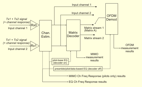
Making an STC/MIMO 2-Channel Measurement
As shown in the simplified block diagram below, the MIMO/STC VSA consists of the standard OFDM Orthogonal Frequency Division Multiplexing: OFDM employs multiple overlapping radio frequency carriers, each operating at a carefully chosen frequency that is Orthogonal to the others, to produce a transmission scheme that supports higher bit rates due to parallel channel operation. OFDM is an alternative tranmission scheme to DSSS and FHSS. demodulator, with additional signal path options that measure input channel 1 or channel 2 from either the RF input or after processing by the matrix decoder.
Matrix Decoder Overview
The Matrix decoder utilized by the OFDMA measurement is not an ideal decoder, but approximates the behavior of a receiver’s Matrix decoding algorithm. Therefore, the resultant RCE metrics from the Matrix Decoder will not match the performance of an ideal implementation of a Matrix A or Matrix B decoder under all channel models or impairments, and can show significant variance. The RCE results from the “Use Matrix Decoder” enabled measurement should be considered qualitative as a validation of the basic MIMO encoding implemented by the transmitter. A traditional BER Bit Error Ratio - A ratio of the number of errors to data bits received on a digital circuit. test with use of channel emulation and an ideal Matrix decoder implementation should be used to fully validate the coding performance of the MIMO transmitter
The VSA’s matrix decoder performs a function similar to the decoder in a WiMAX subscriber unit. Starting from two input signals (each of which contains a combination of the Ant-0 and Ant-1 transmit streams), it mathematically separates the streams from each other, so that they can be individually demodulated and analyzed.
Use Direct measurements (Decoder OFF) when:
- Signals are well-isolated from each and do not require separation, such as when using hardwired connections from the transmitters directly to the VSA input(s).
- Your test procedures require that any cross-transmitter leakage (crosstalk) be counted in the RCE/EVM Error vector magnitude (EVM): A quality metric in digital communication systems. See the EVM metric in the Error Summary Table topic in each demodulator for more information on how EVM is calculated for that modulation format. results. (E.g. as required by the WiMAX RCT).
Use Decoded measurements (Decoder ON) when:
- The input signal(s) contain a combination of both transmitted streams and the stream parameters (power, RCE, flatness, etc.) are to be viewed individually.
- Not connected directly to the TX outputs, e.g. for signals measured “off the air”, or following a real or simulated transmission channel.
- Measuring Matrix A (STC/MISO) signals with a single VSA input.
MIMO and STC Measurement Parameters and Trace Data Information
See Also
About 802.16 OFMA Measurements
About Option B7Y IEEE 802.16 OFDMA Modulation Analysis